 Tuesday, 30 September 2008
This is the third in a series of technical notes outlining the Shlaer-Mellor and Executable UML notation supported by OOA Tool. This technical note covers Subsystem Communication Models (SCM) which are used to show the subsystems within a domain and identify any asynchronous communications between those subsystems. The model itself is automatically derived. However, OOA Tool currently requires someone to layout the model since automatic layout of diagrams where all nodes are connected in many ways is incredibly difficult to perform.
Executable UML [xtUML02] does not name SCMs explicitly. However, diagrams in UML are generally called diagrams, not models. Furthermore, Object Communication Models are called Collaboration Diagrams in Executable UML while Collaboration Diagrams are now called Communication Diagrams in UML2. Thus, the name Subsystem Collaboration Diagram is used here when referring to an SCM in Executable UML notation while the name Subsystem Communication Diagram is used instead in Executable UML2 notation. The other Executable UML variant [xUML04] doesn't seem to use SCMs at all.
Below is an example Subsystem Communication Model in Shlaer-Mellor notation taken from [OOA91] (see page 153):
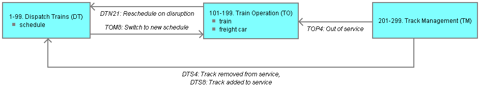
Subsystem Communication Models are very similar to Subsystem Relationship Models and Subsystem Access Models. They all represent subsystems using rectangle shapes containing the subsystem name, optional prefix letters and an optional number range along with prominent object names (prefixed by square bullets). The relative position of the prefix letters and number range was reversed in OOA10 compared to OOA91. OOA10 adopts a format consistent with that used for Objects within Object Information Models. Showing prominent object names in subsystem shapes is also a new feature of OOA10.
All internal asynchronous communications (i.e. internal events generated within state actions) from state models in a source subsystem to state models in a target subsystem are listed on a single rectilinear link with an arrow pointing to the target subsystem. Only the meaning of internal events is shown, i.e. supplemental data items are not shown on SCMs. Any asynchronous communications going in the opposite direction are listed on another rectilinear link with an arrow pointing in the opposite direction. These links only exist if one or more asynchronous communications exist. However, since subsystems within a domain are peer-to-peer, there may be many such links in a typical domain.
Asynchronous communications between subsystems and terminators (which are subsystem independent) are not shown on SCMs in OOA91. They are currently not shown on SCMs in OOA10 either. However, this may change in the future. There is a need to capture the external interface to a domain. This could partially be accomplished by showing external events (those generated outside the domain or within synchronous service actions) from terminators to subsystems and domain-crossing events from subsystems to terminators on SCMs.
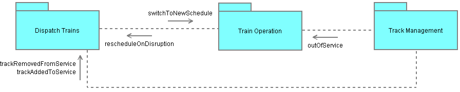
The Shlaer-Mellor example above is shown below in Executable UML notation:
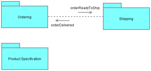
Another example Subsystem Collaboration Diagram taken from [xtUML02] (see page 273) is shown below:
Subsystem Collaboration Diagrams are very similar to Subsystem Relationship Diagrams and Subsystem Access Diagrams. They all represent subsystems using folder shapes containing the subsystem name. Prominent objects are not currently shown.
Subsystem dependencies listing asynchronous communications are represented using short dashed rectilinear links. The internal events are shown on a floating arrow pointing at the target subsystem. Unlike Shlaer-Mellor SCMs, there is never more than one link between any two subsystems, i.e. two links between a particular pair of subsystems in Shlaer-Mellor are replaced with two floating arrows on a single link in Executable UML.
Finally, the Shlaer-Mellor example above is also shown below in Executable UML2 notation:
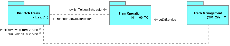
Subsystems are still represented using folder shapes containing the subsystem name. However, the subsystem name is now shown in bold. Furthermore, the subsystem's optional prefix letters and number range is now shown as a right aligned UML property string below the subsystem name. This is consistent with how key letters and numbers are shown on class shapes within Class Diagrams.
Subsystem dependencies are still represented using short dashed rectilinear links. However, a consistent dash length is used across all package diagrams in Executable UML2. See page 43 of [UMLManual05] for an example UML2 package diagram. More significantly, the single floating arrows at each end of these links are replaced with multiple leading or trailing arrows (one per event). In UML2, events going in both directions can be listed together in sequence number order since each event is prefixed or suffixed with an arrow indicating the event's direction. However, sequence numbers are not used in Executable UML. Thus, OOA Tool keeps events which are going in the same direction together and separated from events going in the opposite direction.